Flashback
3-Hold Model for Strength Analysis
The region of failure was identified by field investigations. So for the finite element analysis, a three hold model was considered. Further conditions taken during the analysis were obtained from Class NK Guidelines for Container Carrier Strength (Guidelines for Direct Strength Analysis, 2012) as shown in Table 1.
 |
| Table 1: Conditions for 3-hold model analysis. (Courtesy: Class NK) |
 |
| Fig. 1: 3-hold model used for analysis. (Photo edited) (Courtesy: Class NK) |
Estimation of Ultimate Strength
The strength of the three hold model was estimated considering uncertainties as shown in Figure 2.
How was the yield stress of the structure calculated? The value of yield stress of the members were obtained from their respective mill sheets. The average of all the yield stress values of the different member materials were calculated and regarded as the mean value of hull girder ultimate strength (μ).
It is important to understand what was done next. Given the fact that the strength of a marine structure follows a probabilistic nature (that can be represented by a Probability Density), it is evident that consideration of mean value alone for determining the ultimate structure is not a valid thing to do. What if the strength of the structure at any point of time, reduces from its mean value? Therefore, it is necessary to determine the minimum ultimate strength of the structure to consider the worst case scenario.
Class NK adopted two different methods to determine the minimum hull girder ultimate strength, an the strengths obtained through each of the two methods were categorized as Case 1 and 2 (will be referred by the same hereinafter).
Case 1- The standard deviation (σ) of the yield strength of the bottom shell plates were calculated from the mill sheet values. The minimum yield stress of the hull girder was defined as the value that was less than the mean by three times the standard deviation, i.e. Minimum yield stress = μ-3σ (Refer to Figure 3)
The hull girder ultimate strength was then evaluated corresponding to the above minimum yield stress of the bottom plating. This ultimate strength was regarded as the minimum hull girder ultimate strength.
Case 2- The hull girder ultimate strength was evaluated corresponding to the minimum yield stress of the bottom plating specified in the mill sheets. The obtained ultimate strength was then regarded as the minimum hull girder ultimate strength.
The obtained values of yield stress (for both the cases) were as shown in Table 2.
Now, in order to find the ultimate strength, a very simple method was adopted: The loads at the time of the accident were known and categorized into the following:
 |
| Fig. 2: Factors affecting uncertainty in strength of the double bottom structure. |
It is important to understand what was done next. Given the fact that the strength of a marine structure follows a probabilistic nature (that can be represented by a Probability Density), it is evident that consideration of mean value alone for determining the ultimate structure is not a valid thing to do. What if the strength of the structure at any point of time, reduces from its mean value? Therefore, it is necessary to determine the minimum ultimate strength of the structure to consider the worst case scenario.
Class NK adopted two different methods to determine the minimum hull girder ultimate strength, an the strengths obtained through each of the two methods were categorized as Case 1 and 2 (will be referred by the same hereinafter).
Case 1- The standard deviation (σ) of the yield strength of the bottom shell plates were calculated from the mill sheet values. The minimum yield stress of the hull girder was defined as the value that was less than the mean by three times the standard deviation, i.e. Minimum yield stress = μ-3σ (Refer to Figure 3)
The hull girder ultimate strength was then evaluated corresponding to the above minimum yield stress of the bottom plating. This ultimate strength was regarded as the minimum hull girder ultimate strength.
 |
| Fig. 3: Graphical representation of Case 1 |
Case 2- The hull girder ultimate strength was evaluated corresponding to the minimum yield stress of the bottom plating specified in the mill sheets. The obtained ultimate strength was then regarded as the minimum hull girder ultimate strength.
The obtained values of yield stress (for both the cases) were as shown in Table 2.
 |
| Table 2: Yield stress for Case 1 and Case 2. |
- Hull weight corresponding to the double bottom structure (known before analysis)
- Hydrostatic pressure corresponding to the full draught (known before analysis)
- Container Loads (known before analysis, based on the loading information at the time of the accident)
- Allowable still water bending moment for hogging (calculated before the analysis, from loads 1, 2 and 3)
- Wave-induced pressure (priorly calculated from Class NK Direct Strength Analysis, 2012)
- Wave-induced vertial bending moment (calculated from IACS UR S11)
- Additional vertical bending moment (due to uncertainties)
 |
| Fig. 4: Sequence of application of load on the model. (Courtesy: Class NK) |
The above method was followed for three conditions:
- When yield strength of the structure was corresponding to the mean value (μ)
- Case 1: Yield strength = μ-3σ
- Case 2
 |
| Table 3: Obtained values of Vertical Bending Moments when the hull girder fractured. |
 |
| Fig. 5: Time vs. Bending moment at the section that suffered failure in the case of average yield stress. (Picture edited) (Courtesy: Class NK) |
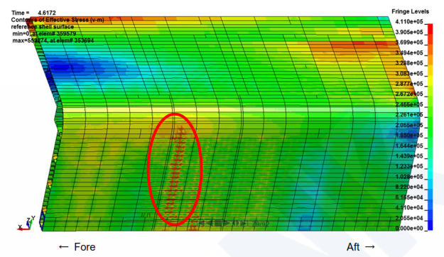 |
| Fig. 6: Von Mises stress at the time of peak load. (Courtesy: Class NK) |
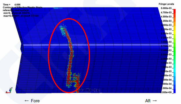
 |
| Fig. 7: Equivalent plastic strain at the time of peak load. (Courtesy: Class NK) |
 |
| Fig. 8: Von Mises stress at the time of peak load. (Courtesy: Class NK) |
 |
| Fig. 9: Equivalent plastic strain at the time of peak load. (Courtesy: Class NK) |
What's in Part 3?
Certain factors were multiplied to the obtained values of bending moment, in order to compensate for the factors of local deformations and residual stresses due to welding. Inclusion of these factors, reduced the strength further. It is on the basis of the then obtained strength values, that the probability and extent of damage will be discussed in the next part of this series.LSD
Article By: Soumya Chakraborty
Thanks Soumya Chakraborty for a very interesting publications of the MOL Comfort case. I have a question: Did you release the part 3? If so, please can you share the link to finish this very detailed and informative report.
ReplyDeleteThanks again. Regards